Tilt Monitoring for Buildings Near Excavation: What You Need to Know
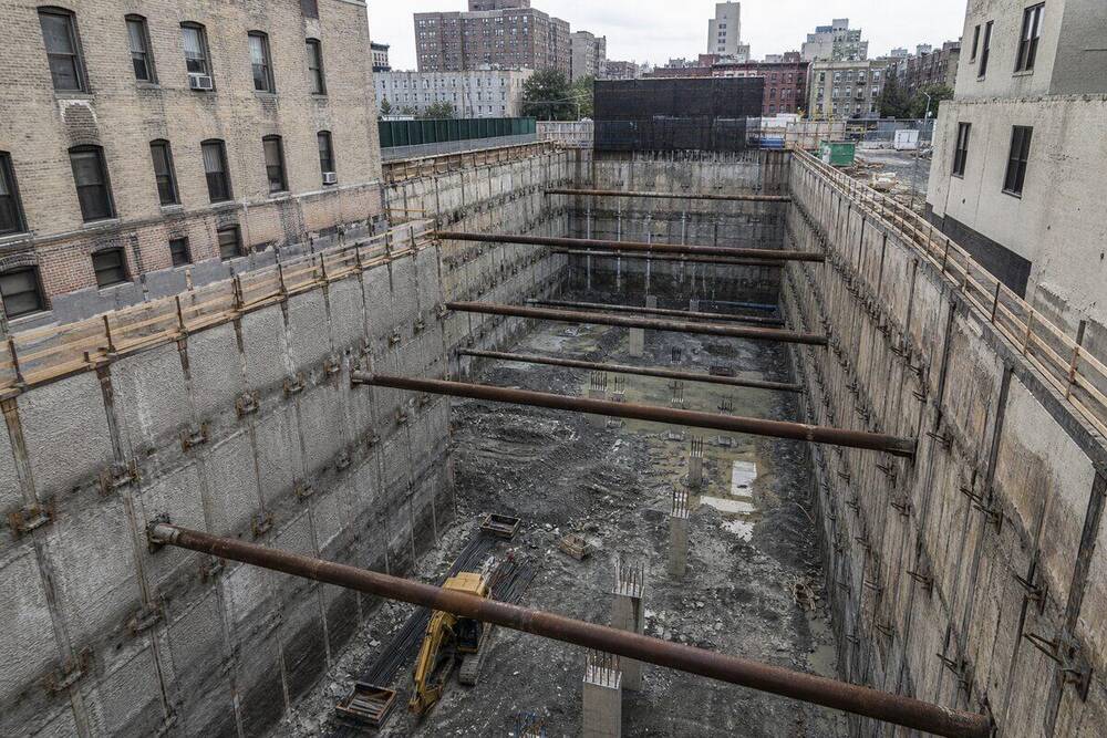
Excavation works impose lateral stress redistribution on surrounding ground, and any structure within the zone of influence will respond with some degree of angular movement. That movement, measured as tilt, is one of the most direct indicators of foundation disturbance, differential settlement, and retaining wall performance. When it goes unmonitored, the first indication of a problem can be visible cracking, door frames racking out of square, or in worst cases, structural distress that triggers stop-work orders and costly remediation. Deploying tiltmeters on adjacent buildings before bulk excavation begins is not a precaution reserved for high-risk projects. It is standard practice on any urban excavation where the zone of influence, typically calculated at 1.5 to 2 times the excavation depth, intersects an existing structure.
The measurement itself is straightforward: a tiltmeter records angular deviation from a reference plane, expressed in milliradians (mrad) or, for construction monitoring purposes, converted to mm/m. One mm/m is equivalent to 1 mrad, which represents 1 millimetre of differential movement across a 1-metre gauge length. At this scale, movements that are imperceptible to the human eye become quantifiable, trend-able, and directly comparable against engineering thresholds derived from structural condition assessments. The challenge is not the physics. It is selecting the right sensor technology, installing it correctly, configuring appropriate alert levels, and having a response protocol in place before the data demands a decision.
Sensor Technologies: MEMS and Electrolytic Tiltmeters
Two sensor types dominate building tilt monitoring in construction environments: MEMS (Micro-Electromechanical Systems) accelerometers configured as inclinometers, and electrolytic tilt sensors. Each has distinct operating principles and practical trade-offs.
MEMS Tiltmeters
MEMS tiltmeters measure the gravitational acceleration vector acting on a proof mass within a microfabricated silicon structure. As the sensor tilts, the component of gravity sensed along each axis changes proportionally to the sine of the tilt angle. Modern MEMS devices resolve angular changes down to 0.001 degrees (approximately 0.017 mrad), with full-scale ranges typically from ±15° to ±90° depending on the application. They are well suited to construction monitoring because they tolerate vibration without damage, draw low power from IoT-compatible supply voltages, and output digital signals (I2C, SPI, or RS-485 Modbus) that integrate directly into telemetry platforms. Their principal limitation is temperature sensitivity: the proof mass suspension and signal conditioning circuitry both exhibit thermal drift, which must be compensated either through onboard algorithms or by logging ambient temperature alongside tilt data and correcting in post-processing.
Electrolytic Tilt Sensors
Electrolytic sensors operate on a different principle. A sealed vial contains a conductive electrolyte and two or more electrode pairs. When the vial tilts, the electrolyte redistributes, changing the resistance between electrode pairs in proportion to the angle. These sensors are extremely sensitive at small angles (resolution down to 0.0001 degrees in precision variants), making them valuable where detecting very early-stage movement is the objective. They are, however, more susceptible to mechanical shock and have a narrower operating temperature range than MEMS devices. In humid or wet construction environments, sealing and housing quality are critical. For permanent or semi-permanent installations on heritage buildings or structures with very low movement tolerance, electrolytic sensors remain the preferred choice where sub-microradian resolution is required.
Biaxial vs Uniaxial Configuration
Both technology types are available in uniaxial (single-axis) and biaxial (dual-axis) configurations. For building monitoring adjacent to excavation, biaxial sensors are standard. Excavation-induced movement is rarely planar: a building may tilt toward the excavation on its primary face while also experiencing minor transverse racking. Capturing both axes simultaneously with a single instrument reduces installation complexity and ensures the vector magnitude of tilt can be calculated rather than inferring behaviour from a single component.
Installation Methodology
Sensor placement determines the quality of data. Poor installation produces noise, drift artefacts, and missed movement that can create false confidence or trigger unnecessary alerts.
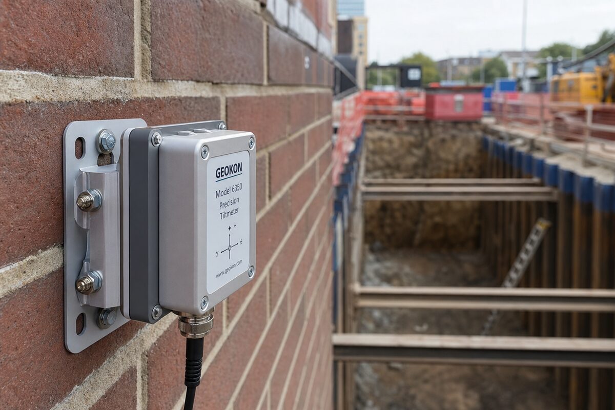
Surface preparation: The mounting surface must be structurally connected to the element being monitored. For column or wall tilt monitoring, sensors are typically bolted to machined aluminium mounting plates epoxy-anchored into the concrete or masonry. Paint, render, and loose surface material must be removed to bare substrate before adhesive or mechanical fixing. Mounting to cladding panels, plasterboard linings, or non-structural elements will introduce compliance errors that corrupt the signal.
Sensor orientation: Each tiltmeter must be levelled and zeroed against a surveyed reference before excavation commences. This establishes the pre-excavation datum. Without a confirmed baseline, there is no way to differentiate construction-induced tilt from pre-existing lean. A digital survey level or precision optical instrument should be used to verify installation angles independently of the sensor's own reading during commissioning.
Sensor locations: On a rectangular building adjacent to an excavation, the minimum installation scheme places biaxial sensors at:
- The basement slab or lowest accessible structural level, as close to the foundation as practical
- Mid-height on columns or walls facing the excavation
- The opposite face of the building, to detect differential behaviour between the near and far sides
On taller structures or those with complex geometry, sensors at each floor level on the excavation-facing facade allow a tilt profile to be developed with height, which distinguishes foundation rotation from upper-storey racking.
Data logging and telemetry: For live construction sites, sensors should transmit data via cellular IoT (4G LTE-M or NB-IoT) or LoRaWAN to a cloud platform. Logging intervals of 15 minutes are typical during low-activity periods, with event-triggered high-frequency capture (1-minute intervals) activating when movement rates exceed a defined threshold. All timestamps must be synchronised to UTC with site local time offset clearly documented, particularly where Queensland Daylight Saving considerations do not apply but interstate project comparisons are being made.
Trigger and Alarm Thresholds
Thresholds for tilt monitoring are project-specific and must be set by the structural engineer of record or a geotechnical engineer with knowledge of the adjacent building's condition, construction type, and foundation system. However, the following values are commonly applied in Queensland urban excavation projects.
Typical threshold framework:
- Alert (Trigger) Level:: 1.0 mm/m cumulative tilt, or a rate of change exceeding 0.2 mm/m per 24 hours. This level prompts engineering review and increased monitoring frequency. It does not constitute structural distress.
- Action Level:: 2.0 mm/m cumulative tilt. This level requires the principal contractor to notify the structural engineer and asset owner immediately, review the excavation programme, and consider implementing additional support measures.
- Alarm Level:: 3.0 mm/m to 5.0 mm/m, depending on building type. At this level, a stop-work assessment is typically required. For unreinforced masonry buildings, the action level may be set lower, at 1.5 mm/m, reflecting their limited capacity to accommodate angular distortion without cracking.
These values correlate with the angular distortion limits for structural damage categories described in Burland and Wroth's foundational work on settlement and distortion, which underpins guidance in AS 5100.3 (bridge design) and is referenced in geotechnical practice documentation across Australian standards frameworks. The specific limit applicable to any structure depends on its damage category assessment, which should be completed and documented before works commence in accordance with the pre-construction condition survey.
Data Interpretation
Raw tilt data from construction environments contains signal components that must be separated before engineering conclusions are drawn.
Thermal cycling: Buildings expand and contract diurnally. On a concrete structure exposed to direct sunlight, daily thermal tilt cycles of 0.2 to 0.5 mm/m are common. These appear as sinusoidal oscillations in the time-series, peaking in the afternoon and recovering overnight. Thermal drift does not indicate structural movement. Interpreting these cycles as excavation response is a common error in projects without adequate engineering oversight. The correction approach is to compare tilt trends at the same time each day (typically 06:00 before solar loading), or to apply temperature compensation using co-located temperature sensors.
Construction vibration interference: Nearby piling, compaction, and demolition generate impulsive and sustained vibration. MEMS tiltmeters with appropriate low-pass filtering (typically a 0.1 Hz to 1 Hz cutoff for settlement monitoring) will not register vibration events as tilt, but lower-quality sensors or poorly configured logging firmware can introduce artefacts. Reviewing vibration data from co-located geophones alongside tilt records helps confirm whether apparent tilt spikes correlate with blasting or impact events, which would indicate an instrumentation issue rather than structural movement.
Trend analysis: Meaningful tilt monitoring is not threshold-watching. The rate of change over time, the correlation with excavation stage, and the spatial pattern across multiple sensor locations are all more informative than any single reading. A structure tilting progressively at 0.05 mm/m per day during a two-week excavation phase presents a different risk profile than one that moves 0.3 mm/m in a single day following a heavy rain event, even if both remain below the action level.
Cross-referencing with other instruments: On well-instrumented projects, tiltmeter data should be interpreted alongside inclinometer profiles in the retaining wall or ground, crack gauge readings on the adjacent structure, and survey prism data. Tilt, crack width, and wall deflection should all trend consistently. Divergence between instruments is a data quality signal that warrants investigation before relying on any single dataset.
Response Protocols When Thresholds Are Exceeded
Exceeding a monitoring threshold is a process trigger, not an emergency declaration. But the process must be defined, documented, and communicated to all relevant parties before excavation begins. In Queensland, this is particularly relevant where development approvals issued by local governments or SARA include condition requirements for adjacent structure protection.
When alert level is reached, the principal contractor should:
- Notify the project structural engineer and the monitoring engineer within the same business day
- Increase logging frequency and review the previous 48-hour trend
- Document the excavation activity at the time of threshold exceedance (excavation stage, dewatering status, surcharge loads near the boundary)
- Confirm sensor function by cross-checking adjacent instruments and reviewing raw voltage or diagnostic outputs
When action level is reached:
- Notify the asset owner or building manager of the adjacent property under the terms of the pre-construction agreement
- Suspend or modify excavation activities on the affected boundary pending engineering review
- Commission an independent structural inspection of the adjacent building
- Review the retaining wall design, propping loads, and any dewatering programme for contributing factors
When alarm level is reached, stop-work on the affected zone is the default position until the structural engineer of record has reviewed the data, inspected the structure, and provided written clearance to continue. In some cases, Queensland Building and Construction Commission (QBCC) notification obligations may be triggered depending on the nature of the structure and the licence category of works.
Documentation and Reporting
All tilt monitoring data, including sensor calibration records, baseline surveys, threshold justifications, and breach notifications, must be retained as project records. For projects involving development approvals with monitoring conditions, the environmental authority or approval holder may require submission of monitoring reports to DES or the relevant assessment manager. Monthly summary reports with time-series plots, threshold overlays, and a written interpretation from the monitoring engineer form the standard reporting format for most Queensland urban excavation projects.
Calibration certificates for each tiltmeter should be current (typically within 12 months of deployment for precision electrolytic sensors, or at the manufacturer's recommended interval for MEMS devices). Post-excavation, a final report comparing pre- and post-construction tilt baselines confirms whether any permanent movement occurred and provides a defensible record in the event of third-party damage claims.
Conclusion
Tilt monitoring on buildings adjacent to excavation works is an engineering discipline that combines sensor selection, precise installation, structured data interpretation, and pre-agreed response protocols. MEMS tiltmeters and electrolytic sensors each have a role depending on the sensitivity required and the environmental conditions on site. Thresholds expressed in mm/m must be set against the structural condition of the specific building, not generic defaults, and the data must be interpreted by engineers who understand thermal noise, vibration artefacts, and the relationship between tilt, distortion, and structural damage. Getting this right before bulk excavation commences is significantly less expensive than managing a dispute over cracking in an adjoining property after the fact. Oculus Technology deploys tiltmeter monitoring systems across Queensland urban construction projects, integrating sensor data with cloud-based telemetry and providing RPEQ-backed interpretation. Further information is available at [oculustech.au/services/tilt-monitoring](https://oculustech.au/services/tilt-monitoring).
Need monitoring for your project?
Share your site context, approval conditions, and project timeline. We'll respond with a practical monitoring scope within 24 hours.
Request a Scope