Bridge Monitoring in Australia: Sensors, Methods, and Case Studies

Bridge infrastructure in Australia carries significant public risk and economic consequence when it deteriorates undetected. Queensland's state-controlled road network alone includes thousands of bridges managed under TMR's asset management framework, each subject to periodic inspection under the *Bridge Inspection Manual* and rated against condition states that drive maintenance programming and load restriction decisions. Where visual inspection reaches its limits, particularly on structures subject to dynamic loading, fatigue accumulation, or scour-vulnerable foundations, instrumented monitoring fills the gap with quantified, time-stamped evidence that inspection observations alone cannot provide.
Structural health monitoring (SHM) applied to bridges is not a single technology. It is a configured system of sensors, data acquisition hardware, telemetry, and analysis software calibrated to answer specific structural questions. The question might be whether a bridge can support a permitted oversize load, whether a fatigue-critical weld detail is accumulating cycles toward its design limit, or whether a pier foundation is losing bearing capacity under sustained flood flow. Each question demands a different sensor type, sampling strategy, and interpretation framework. Getting that configuration right before deployment is the engineering work that determines whether the data produced is actionable or merely voluminous.
The regulatory context in Australia adds a layer of specificity that general SHM literature rarely addresses. TMR's *Structures Technical Standards* suite, including the MRTS series applicable to construction works on state-controlled roads, sets requirements for monitoring during construction that affect temporary works, falsework, and adjacent infrastructure. DES and local government development approvals can impose vibration and settlement monitoring conditions on bridge works near sensitive receivers. The intersection of these obligations with the technical capability of modern sensor systems is where monitoring engineers spend most of their time.
Sensor Types and Their Structural Roles
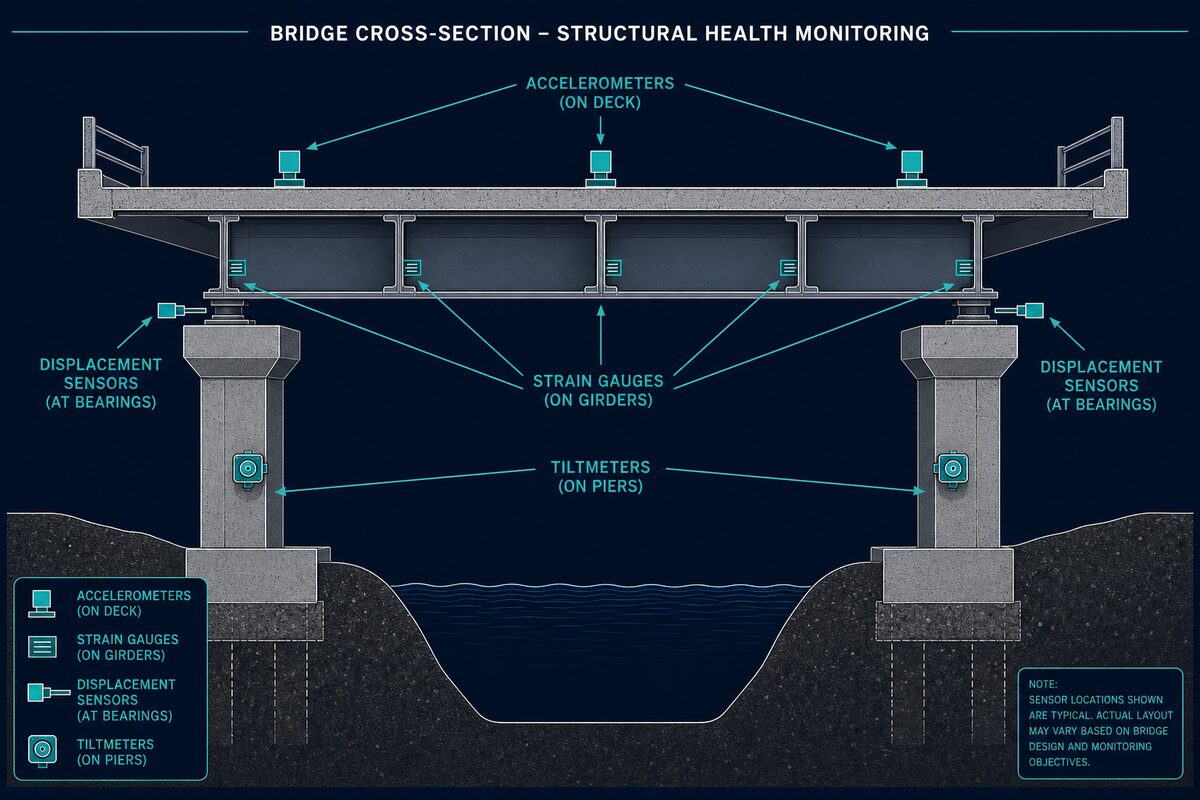
Selecting sensors for bridge monitoring requires matching the physical measurement to the structural parameter of interest. A single bridge may require four or five distinct sensor types operating simultaneously, each addressing a different failure mode or assessment objective.
- Strain gauges (foil and vibrating wire):: Measure microstrain at a point on a structural member. Foil gauges offer high-frequency response suitable for dynamic load events; vibrating wire gauges provide stable long-term readings for static load or temperature effects. Both require temperature compensation. Typical bridge applications include monitoring at fatigue-critical weld toes, mid-span flexural zones, and bearing contact areas.
- Triaxial geophones and MEMS accelerometers:: Capture dynamic response under traffic, wind, or seismic loading. Geophones are velocity-based and well-suited to construction vibration (measured in mm/s PPV against AS 2187.2 and DIN 4150-3 thresholds), while MEMS accelerometers suit ambient vibration testing and operational modal analysis.
- Tiltmeters and inclinometers:: Quantify rotation at bearings, abutments, and pier caps. Readings in millidegrees detect differential settlement or bearing lock-up that would not register on visual inspection.
- Crack gauges (displacement transducers):: Monitor crack width change in concrete members or fatigue crack propagation in steel. Output in millimetres across a defined gauge length.
- Linear potentiometers and LVDTs:: Measure bearing displacement, expansion joint movement, and relative movement between structural elements. Essential for detecting restrained thermal expansion or bearing seizure.
- Piezometers and scour sensors:: Monitor water pressure adjacent to pier foundations and detect bed level change. Sonar-based scour sensors measure riverbed elevation in real time.
- Fibre Bragg grating (FBG) arrays:: Distributed strain and temperature sensing along a single fibre, particularly useful for long-span or box girder bridges where spatial resolution of strain distribution is needed.
Fatigue Monitoring and Cycle Counting
Steel bridges and composite structures accumulate fatigue damage as a function of stress range and cycle count at critical details. AS 4100 and the fatigue design provisions it references identify detail categories with finite life curves (S-N curves). Once a bridge is in service, the actual loading spectrum it experiences rarely matches the design spectrum, making in-service strain monitoring the most reliable method for assessing remaining fatigue life.
Fatigue monitoring programmes typically instrument weld details with foil strain gauges sampling at 100-500 Hz to capture the full stress history under traffic loading. Rainflow cycle counting algorithms then process the strain time-series into stress range histograms that can be applied to the relevant S-N curve. Where a detail is found to be accumulating cycles faster than the design assumption, options include load restriction, weld repair, or planned decommissioning. Where the measured spectrum is less severe than assumed, the assessment supports extended service life, which has direct financial value to the asset owner.
TMR's load posting and de-posting process draws on exactly this kind of data. Monitoring evidence that quantifies the actual stress response to a specific vehicle configuration can inform a load rating review under the *Bridge Assessment Manual* in a way that conservative analytical assumptions cannot.
Scour Detection at Vulnerable Piers
Scour is the leading cause of bridge failure in Australia and globally. It occurs when flood flows erode riverbed material from around bridge foundations, reducing the embedded depth of piles or footings until lateral or vertical capacity is lost. The problem is that scour holes often partially or fully refill with sediment after a flood event, leaving no visible evidence at the time of post-flood inspection.
Continuous scour monitoring using tethered float systems, magnetic sliding collar sensors, or fixed-mount multibeam sonar provides real-time riverbed elevation data at the pier. When bed level drops below a threshold corresponding to a calculated critical scour depth, the system triggers an alert, enabling a load restriction or temporary bridge closure decision before structural capacity is compromised. Piezometers installed in the foundation zone complement scour sensors by detecting changes in pore water pressure distribution that accompany scour progression.
TMR requires scour assessments for structures on waterways classified as scour-critical, with monitoring systems increasingly specified in place of or alongside periodic sonar surveys. For bridges on railway corridors managed under Queensland Rail's infrastructure standards, real-time scour monitoring is tied directly to track possession and emergency response protocols.
Bearing Displacement and Deck Movement
Bridge bearings are designed to accommodate thermal expansion, rotation under load, and longitudinal movement due to traffic braking and acceleration. When bearings seize, corrode, or accumulate debris, the movement they were designed to allow is instead transferred as force into the substructure, potentially causing cracking in pier caps, abutment walls, or deck soffits.
Instrumented monitoring of bearing displacement uses LVDTs or short-stroke potentiometers mounted to measure relative movement between the bearing plate and the supporting element. Readings logged against temperature allow the engineer to construct a thermal movement signature. Departure from the expected linear relationship between temperature and displacement indicates restrained movement, which can be cross-referenced with strain data at the abutment or pier cap to quantify the additional force being generated.
Expansion joint monitoring follows the same principle. Displacement sensors across the joint gap, combined with temperature and traffic load data, confirm whether the joint is performing within design limits or whether deck profile changes are creating dynamic impact loading at the joint edge.
Dynamic Load Testing and Modal Analysis
Dynamic load testing involves instrumenting a bridge with accelerometers and strain gauges, then passing controlled vehicle loads across it at defined speeds and axle configurations. The response data is used for two distinct purposes: direct load-rating support and calibration of a finite element model.
Load Rating Support
Measured strain and deflection under a known vehicle weight and configuration allows direct calculation of load distribution factors and dynamic amplification factors (DAFs) specific to the structure. These measured values often differ substantially from code-default values used in desk-based assessments. Where measured DAFs are lower than assumed, the effective load rating of the bridge increases. This is particularly relevant for older structures where conservative assessment has resulted in unnecessary load restrictions affecting freight and oversize vehicle movements.
FE Model Calibration
Operational modal analysis (OMA) extracts the natural frequencies, mode shapes, and damping ratios of a bridge from its ambient vibration response under traffic and wind. These modal parameters are then used to calibrate a finite element model so that the model replicates the observed structural behaviour. A calibrated model supports scenario analysis, including the effect of proposed increased loads, member deterioration, or modification to the structure.
Modal parameter tracking over time also provides a condition indicator. A reduction in natural frequency at a specific mode, or a change in mode shape, indicates a stiffness reduction somewhere in the structure. Combined with visual inspection findings and the TMR condition state framework, this change in modal signature can be mapped to a specific deterioration mechanism.
TMR Compliance and MRTS Requirements
TMR's *Structures Technical Standards* and the MRTS specifications govern construction activities on state-controlled road infrastructure. MRTS71 (Existing Bridges and Structures) requires that monitoring and protection measures be in place when construction activities could affect bridge structural integrity. This includes vibration monitoring against specified PPV limits during piling, demolition, or blasting near existing structures, and settlement monitoring when excavation or surcharge loading occurs within the influence zone of bridge foundations.
For construction monitoring, TMR typically requires the installation of monitoring instrumentation before works commence, with threshold levels and response protocols documented in a Construction Traffic Management Plan or Structural Monitoring Plan submitted to and approved by the relevant TMR regional office. Data must generally be available to the project superintendent in near-real time, with automatic alerting when threshold values are exceeded.
SARA (State Assessment and Referral Agency) referral conditions under the Planning Act 2016 may impose additional monitoring requirements on development projects near state transport infrastructure, including bridges. These conditions are project-specific and can include post-construction monitoring periods extending beyond practical completion.
Condition State Assessment and SHM Data Integration
TMR's *Bridge Inspection Manual* uses a condition state scale (typically CS1 to CS4 or CS0 to CS5 depending on the element) to record the observed condition of each bridge element during periodic inspection. These condition states feed into the Bridge Management System and drive maintenance priority and budget allocation decisions.
SHM data does not replace visual inspection within this framework, but it substantially improves the confidence with which condition state assessments are made and the rate at which deteriorating trends are detected between inspection cycles.
Practical integration of SHM data into condition state assessment involves several steps:
- Baseline establishment:: Monitoring during or immediately after major maintenance or strengthening work establishes a reference condition against which subsequent data is compared.
- Trend analysis:: Automated trend detection on long-term data streams from vibrating wire strain gauges, tiltmeters, or crack gauges identifies gradual change that would not be visible in a point-in-time inspection.
- Event correlation:: Data from dynamic load events, flood flows, or seismic activity is reviewed against thresholds to determine whether the structural response fell within expected bounds. Exceedance of threshold values is flagged as a prompt for targeted inspection.
- Condition state justification:: Where SHM data shows stable or improving structural behaviour, it supports a more favourable condition state assignment than visual evidence alone might justify, avoiding unnecessary maintenance expenditure. Conversely, anomalous sensor data can trigger an intermediate inspection and early intervention, preventing condition state escalation to CS4 or CS5.
The bridge owner or managing authority benefits from a documented evidence trail that connects sensor readings to maintenance decisions, which is increasingly required for asset management due diligence and infrastructure investment submissions.
Data Management and Reporting
A monitoring system that generates data without a structured analysis and reporting protocol provides limited operational value. For bridge SHM, the data management framework typically follows principles aligned with ISO 13374 for condition monitoring of machines, adapted to civil infrastructure. Key elements include automated data quality checking, sensor health monitoring, threshold-based alerting, and periodic reporting at intervals matched to the monitoring programme objectives.
Cloud-hosted data platforms with real-time dashboards allow project managers, principal contractors, and asset owners to view current readings and recent trends without requiring direct access to the instrumentation or specialist software. Alert notifications via SMS or email, triggered when measurements exceed pre-defined thresholds, enable prompt response without continuous manual data review. At [Oculus Technology](https://oculustech.au/services/structural-health-monitoring), our SHM deployments include configurable alerting protocols calibrated to the specific thresholds in the project's monitoring plan, whether those thresholds are set by TMR approval conditions, the structural engineer of record, or the asset owner's risk tolerance.
Reporting formats should distinguish between routine compliance reporting, which confirms that measurements remain within acceptable bounds, and exception reporting, which provides structured engineering analysis of an anomalous event and recommends a response action. Both serve different audiences: compliance reports address the approval authority or client; exception reports go to the structural engineer and asset owner with enough technical detail to support a decision.
Conclusion
Bridge monitoring in Australia operates at the intersection of structural engineering, sensor technology, data management, and a specific regulatory environment that most generic SHM literature does not address. The instruments, whether strain gauges on fatigue-critical welds, scour sensors at flood-vulnerable piers, or accelerometers for modal testing, are the means to an end. The end is a quantified, defensible picture of structural behaviour that supports load rating decisions, maintenance planning, TMR compliance, and long-term asset management.
Effective monitoring programmes are designed around a structural question, not around sensor availability. When that discipline is applied, SHM data integrates directly into the TMR condition state framework, informs load restriction decisions with measured evidence, and gives bridge owners the confidence to manage assets based on actual behaviour rather than conservative assumptions. For structures approaching the end of their design life or subject to increasing freight loads, that data is often the difference between a premature replacement programme and a well-supported extension of serviceable life.
Need monitoring for your project?
Share your site context, approval conditions, and project timeline. We'll respond with a practical monitoring scope within 24 hours.
Request a Scope